The Key Principles of Frameless Motor Mounting and Installation
Discover the key principles of frameless motor mounting and installation. Learn best practices to optimize performance and ensure seamless integration for your applications.
July 17, 2024
.avif)
A frameless motor consists of just the active parts of the rotor and stator without an external housing, bearings, and shaft.This makes them ideal for direct integration into the mechanical structure of the device they drive. Thanks to the advantages of FiberPrinting Alva’s slotless frameless motors have extremely thin active parts (Fig.1), making them even more attractive for any kind of integrated solutions. Moreover, slotless motors are less sensitive to radial misalignment between the rotor and the stator, which in certain cases will simplify the task of their integration.
.png)
In many applications the use of frameless motors may bring benefits such as improved system performance, reduced maintenance, smaller mechanical footprint, and higher system efficiency. While the benefits are well understood, the practical questions related to mounting, installation and integration should be answered. This article will describe some of the key principles. It includes descriptions of common methods of installing and retaining frameless stators into housings and rotors onto shafts. General handling, safety and storing information is also provided.
Important pre-installation considerations
Thermal management: Plan for adequate cooling, as frameless slotless motors generate heat similar to other motors.
Electrical interface: Verify the motor's electrical specifications and ensure compatible electronic controller.
Mechanical structure: Ensure the structure can support the motor's weight, torque output and dynamics of the motion if the installation is not stationary.
Safety precautions
The frameless motor rotors contain high energy rare-earth magnets that produce strong magnetic fields. Therefore, anyone having active implants, such as pacemakers, should keep a safe distance from the rotors of these motors.
The rotors create strong magnetic attractive forces, attracting ferromagnetic materials, such as many of metals, which can result in uncontrolled movement of the magnetic items resulting in collisions between them and the rotor. Therefore, precautions should be taken to remove all other potentially magnetic items from within an area equal to approximately 3 times the diameter of the rotor.
Strong magnetic fields produced by the rotor magnets may affect or damage electronic devices and measuring equipment. Rotors should not be placed close to computer disks, computers, monitors or credit cards, etc.
Handling and storage
Handling and storage of motor components is very important. It is recommended that stators and rotors be stored in their original packaging until installation is required. Special care must be taken while handling stator assemblies. Damage to the coil insulation and lead wires can result in electrical shorts and possible electrical shocks. Precautions must also be taken while handling the rotor assembly, as strong magnet forces are present. Magnets can be chipped, cracked or broken if the rotor is dropped or large magnetic objects and other rotors are suddenly attracted to the rotor.
Stator mounting into the housing
General considerations
Since Alva’s motors are self-sufficient magnetically, there is no concern or requirement to have a soft-magnetic outer housing on the motor. Most mechanisms employing the small motors use aluminium housing, but it can be made of any material suitable for the customer’s environment and application.
It is good practice to design any metal surfaces to be 2-3 mm away from the motor windings in all directions for electrical insulation purposes. The windings should not be in direct contact with any of the metal housing surfaces. Extra axial room is required where the leads of the motor exit. A small cavity with an associated hole to bring the leads out is necessary.
If grounding is required, a ground stud can be placed on the housing. While this is not exactly at the same voltage potential as the stator stack, it does represent a typical grounding scheme observed in most motors with two or three part housings. A ground stud is typically only required when the motor is going to operate with no isolation between the mains and the electronic speed controller.
Stator retention within the housing
There exist several concepts for stator mounting into housings. The approaches can be based on bonding, clamping or shrink fit. They are presented below on conceptual level. In the figures below illustrating the methods, the housings with other elements, e.g. bearings, are shown for general illustrative purposes. There can be many different variations of housing designs.
Press-fit stator retention
Designing an interference fit between the stator and the housing, and installing the stator by pressing it into the housing is not recommended for Alva’s frameless motors. If the motor is to be operated over a wide environmental/operating temperature range, use of an interference fit often limits the choice of housing materials to those with coefficients of thermal expansion (CTE) that match the lamination material’s CTE. Another issue regarding the press method/design are that burrs can be created. These burrs have the potential to become slivers of metal that can lodge into windings and cause electrical failures. In addition, the lamination stack may “crack” or “split” if the pressing direction isn’t well controlled and the stack is not inserted perpendicular to the housing bore.
Heat shrink fit stator retention
This method involves heating the aluminium housing and placed over the stator. Similar to press-fit, this method is also based on designing an interference fit between the stator and the housing, and suffers the same drawbacks related to CTE matching and potential limitations of material selections.
Alva does not recommend this method as the sole means of retention. A light interference fit combined with an adhesive bond as described below is a more reliable method.
Adhesive bonded stator retention
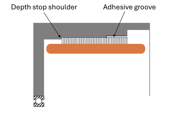
Adhesive bonding is one of the most common methods of stator retention and is recommended by Alva in many applications. Adhesive bonding allows for the use of almost any material for the housing.
The housing should be designed with a 0.2-0.3 mm adhesive groove covering 50% to 75% of the axial length of the stator lamination stack. The adhesive groove can be centered axially on the stack or located to oneside.
The preferred installation process, performed with either of the two recommended epoxies, consists of heating the housing to 100°C or higher, quickly applying the adhesive to the adhesive groove in the hot housing, and immediately inserting the stator. The assembly is then cured at the epoxy cure temperature. The advantage of this method is that the housing bore can be designed to be a line-to-line or light/transitional interference fit with the stator, depending on the housing material selection and material coefficient of thermal expansion. The adhesive cures in the expanded state and is under compression at all other temperatures.
If the housing cannot be heated prior to the stator installation, then the housing bore should be designed to be at least 0.003-0.005 mm larger than stator outer diameter under worst case tolerance conditions.
Alva can be consulted for selection of an appropriate adhesive. However, 3M DP420 and Hysol E40HT are both good general purpose, toughened structural adhesives that can be used in most applications.
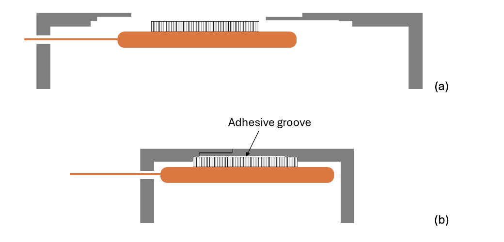
The stator can be fixed in a regular housing and bonded with an adhesive as shown in Fig. 2.
The more concept with overlapping end cups and the use of bonding adhesive is presentedin Fig. 3. With this concept is important to ensure that the stator is aligned correctly with the mounting points.
Axial clamping stator retention
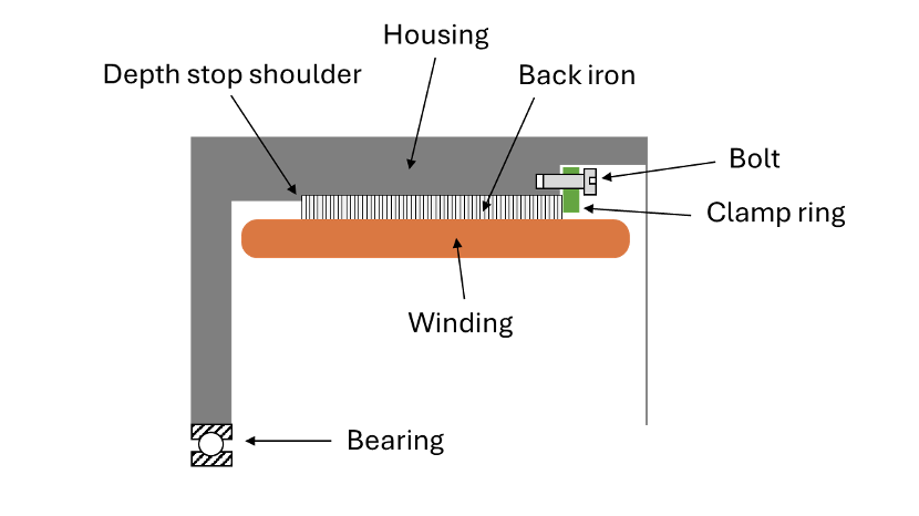
An axial clamping mechanism is also commonly used for stator retention. Alva’s frameless motor stators have a bare steel banking surface on both sides of the stator. The stator is installed into the housing and seated onto the housing banking surface.
A clamping ring should be designed that engages the top exposed banking surfaces and applies axial pressure by being bolted into the housing. An axial clamp can be either a full 360° ring or a few “servo clamps” applying axial pressure to the stator stack to hold it in place.
One possible concept is presented in Fig. 4. It is designed for easy removal or maintenance access. The locating shoulder should be used for precise location of the stator. The gap behind the clamp ring should be maintained to allow for compression on stator. At least half of the stator back iron should be engaged with the clamping ring.
There can be used mounting bolts and washers to secure the stator. Best engineering practices should be followed for determining the number and size of clamping ring bolts as required for the torque capacity of motor. The bolts should be tightened to the specified torque.
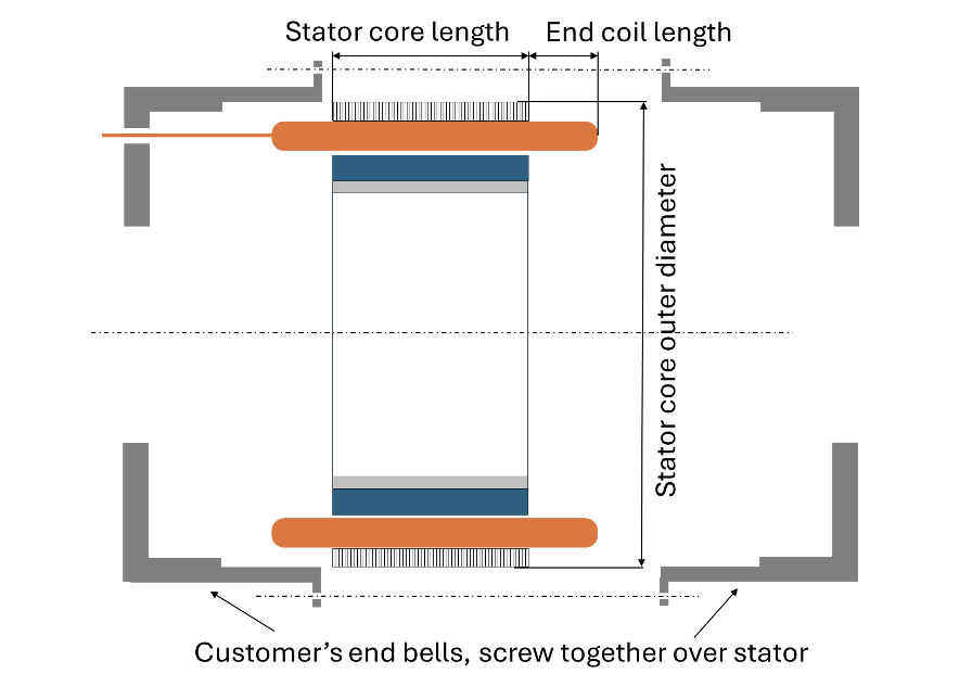
In another variant the stator assembly can be mounted between two end bells (Fig.5). End bells can be produced by either machining a solid piece of stock or through a die-casting process. In either case the end bells must be designed to provide a rigid and stable support for the stator and rotor assembly. The concept is good for easy removal or maintenance access.
Bolt–in stator retention
Alva’s frameless motor stators are not typically retained via bolts running through holes in the lamination stack since the laminated ring is so thin. Alva does not recommend this method for Alva’s motors.
Custom solutions
Solutions with tighter integration with the housing where back iron is installed into the customer’s housing (Fig. 6) and then the winding is inserted and molded in situ, are possible on request.
Rotor mounting
It is worth noting that the rotor carrying structure can be non-magnetic since in Alva motors there are used Halbach magnet arrays on the rotor, so there is no need for back iron.
Rotors can be mounted to shafts by various methods like those for the stators. Expected torque loads and joint strengths of the different retention options should be considered when designing and choosing the rotor to carrying structure interface method.
Press-fit
One press-fit method involves holding the rotor to the carrying structure with an interference fit between a set of serrations on the carrying structure and the rotor inner circumference. A set of 4 serrations equally spaced around the outside diameter of the carrying structure is usually required. Serration length should be no less than ¾ the length of the rotor. A tapered serration is acceptable.
The rotor’s inner diameter should be equal to the carrying structure outer diameter. The clearance range between the rotor and the carrying structure should be between 0.005 and 0.05 mm.
Another press-fit method employs an intermediate component called a tolerance ring and the carrying structure having a special feature where the tolerance ring is placed.
Care should be taken during the press operation to only press upon the carrying ring of the rotor– not on the magnets.
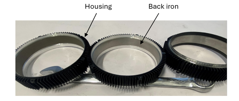
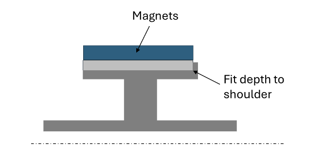
The carrying structure can have a shoulder element to ensure proper positioning of the rotor (Fig. 7).
Heat shrink fit
In this method the carrying structure is cooled to achieve a clearance fit and then the rotor is installed onto the carrying structure. Like press fit, this method is also based on designing an interference fit between the rotor and the carrying structure. Heating the rotor is not recommended, since there is a risk of permanent demagnetisation of the rotor magnets.
Adhesive bonding
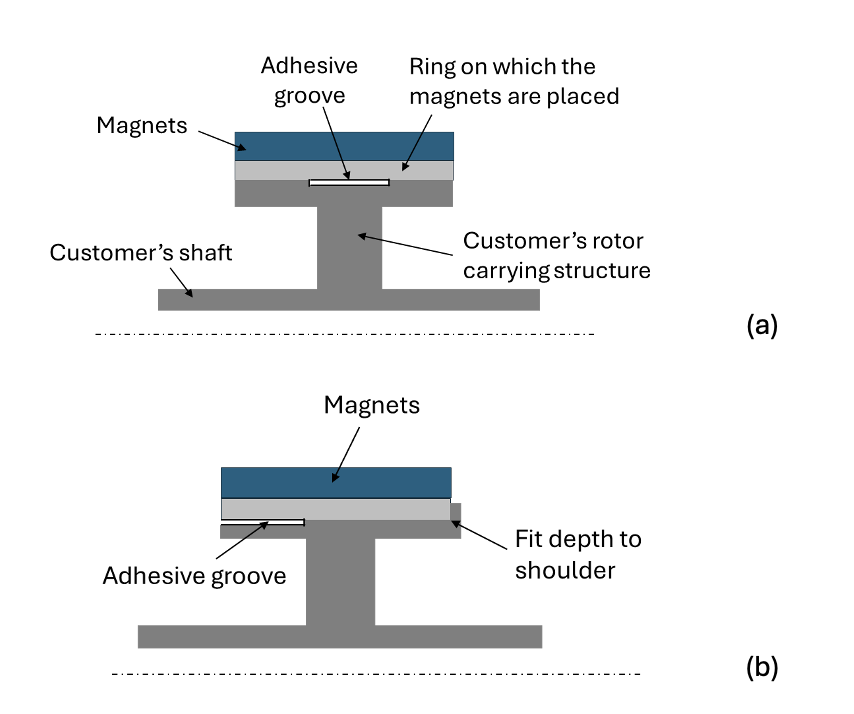
This method involves holding the rotor to the carrying structure with a high strength retaining compound (i.e. 3M DP420, Hysol/Loctite E40HT, Loctite 648 or similar epoxy based structural adhesives). Adhesive manufacturers produce retaining compounds should be consulted to help select the correct retaining compound for the application in question. Adhesive groove should be arranged - two variants are shown in Fig. 8, however, there are many other possible variants. The recommended depth of the adhesive groove on the rotor mating part is usually 0.2-0.3 mm. The length of the adhesive groove can be 50%to 75% of the axial length of the rotor.
Adhesive bonding allows the use of almost any material for the mating structure. Differences in coefficients of thermal expansion and expected operating temperatures should always be taken into consideration.
Axial clamping
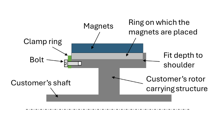
This method involves holding the rotor in place with force exerted through a clamp ring. A lock washer or bonding agent can be applied to prevent the screw from becoming loose. The number of screws will depend on the size of the rotor, torque requirements and customer application. It is critical not to clamp on the magnet material because it is very brittle. The clamping should be applied to the magnet carrying ring as shown in Fig. 10.
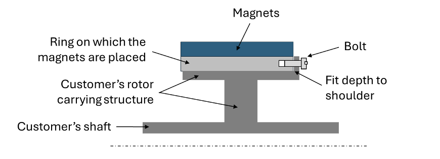
Bolt–in rotor retention
In this method the rotor is bolted to a mating element of the carrying structure as shown in Fig. 11. Alva’s standard magnet carrying rings are thin and do not have additional mounting features. However, custom rings with customer-specified mounting features and bolt-hole patterns are an option that can be discussed with the factory.
Key-way retention
Alva standard magnet carrying rings do not have keyways. However, customers can contact Alva and order special custom ring configurations if desired. Alva do not normally recommend keys as a rotor retention solution for several reasons: it is typically an expensive feature to add, it requires a thicker ring cross-section, it still requires some means of axial clamping, and for smaller motors, it is overdesigned with respect to typical torque loads.
Custom solutions
Alva can mount magnets directly onto custom hubs and provide complete custom assemblies; thereby reducing the number of parts and assembly operations.
Some practical aspects of putting the stator and the rotor together
Magnetic attractive forces: Between the rotor and stator can be high, so it is very important that caution and care be taken when assembling the two parts. To protect both the magnets and the stator winding from damage a thin non-magnetic sleeve (or equivalent) can be used to wrap around the rotor during the installation process. Once the rotor is installed in the stator, and the assembly is complete, the sleeve can be removed.
Alignment: Ensure the rotor and stator are precisely aligned to avoid imbalances.
Free rotation: Ensure it rotates freely without contact.
Some post-installation checks
Temperature monitoring: Check the motor and gearbox temperatures during initial operation to ensure adequate cooling.
Testing: Power on the motor and perform initial tests to ensure proper operation and rotor-stator alignment.
Vibration check: Monitor for any unusual vibrations which could indicate misalignment.
For any questions regarding the installation process or design features for mating parts, contact Alva Industries.

All rights reserved ©2025