The Key Principles of Frameless Motor Integration with Gearboxes
Discover key principles for seamless frameless motor integration with gearboxes. Maximize efficiency and performance with tips on design, mounting, and alignment.
July 24, 2024
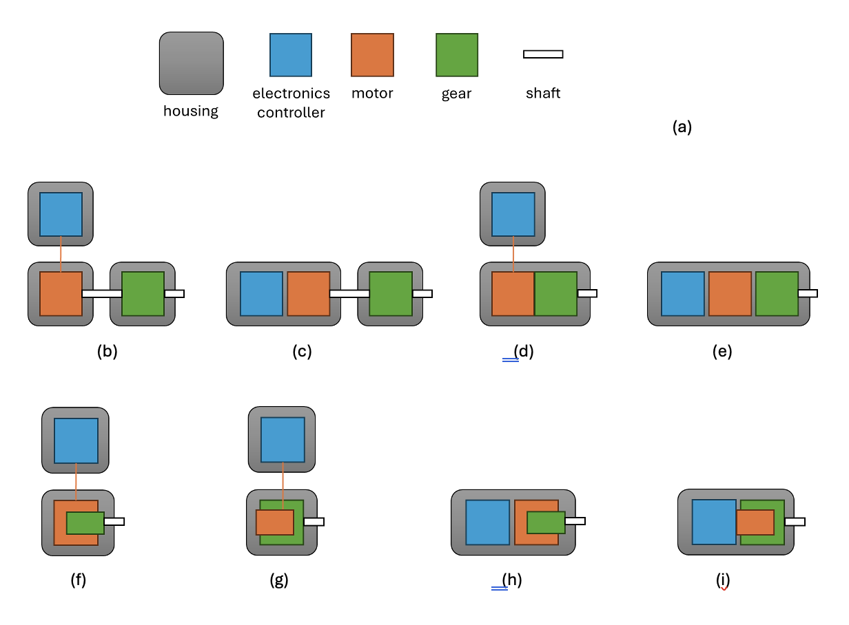
Variable speed drives with permanent magnet motors use electronic speed controllers (frequency converters) and are often paired with gearboxes. Fig. 1 covers all theoretically possible variants of separate installation or integration of the three main components: motor, controller and gear. The legend is presented in Fig. 1, a. One can call a solution “integrated” when housings of the components are in direct contact, or the components share the same housing. For example in Fig. 1, c the motor and controller share the same housing but the gear is in a separate housing the there should be used some coupling device to connect it to the motor. A controller is always connected to a motor via a cable, but in integrated solutions, the cable is so short that it can be disregarded as part of the installation process.
Integration of the electronics, brakes and sensors is not regarded in this document. The focus is instead on variants of integration of motors with gearboxes corresponding to Fig. 1, d-i. A motor and a gearbox can be very tightly integrated, as will be shown below. In Fig. 1, d-e the motor and the gear share the same housing (or two directly connected housings) but are mounted next to each other. In Fig. 1, f and 1, h the gear is integrated inside the motor and in Fig. 1, g and 1, i the motor is integrated inside the gear. The system variants presented in Fig. 1, h-i can be called “fully integrated”.
To integrate a frameless motor with an existing gearbox, there should be created a new mechanical structure for holding the stator and the rotor of the motor. When designing the structure one can use some of the solutions presented in the guidelines for mounting and installation of the frameless motors. The new structure should also have the right interface for connection to the particular gearbox or a series of gearboxes.
Mounting a motor to a gearbox
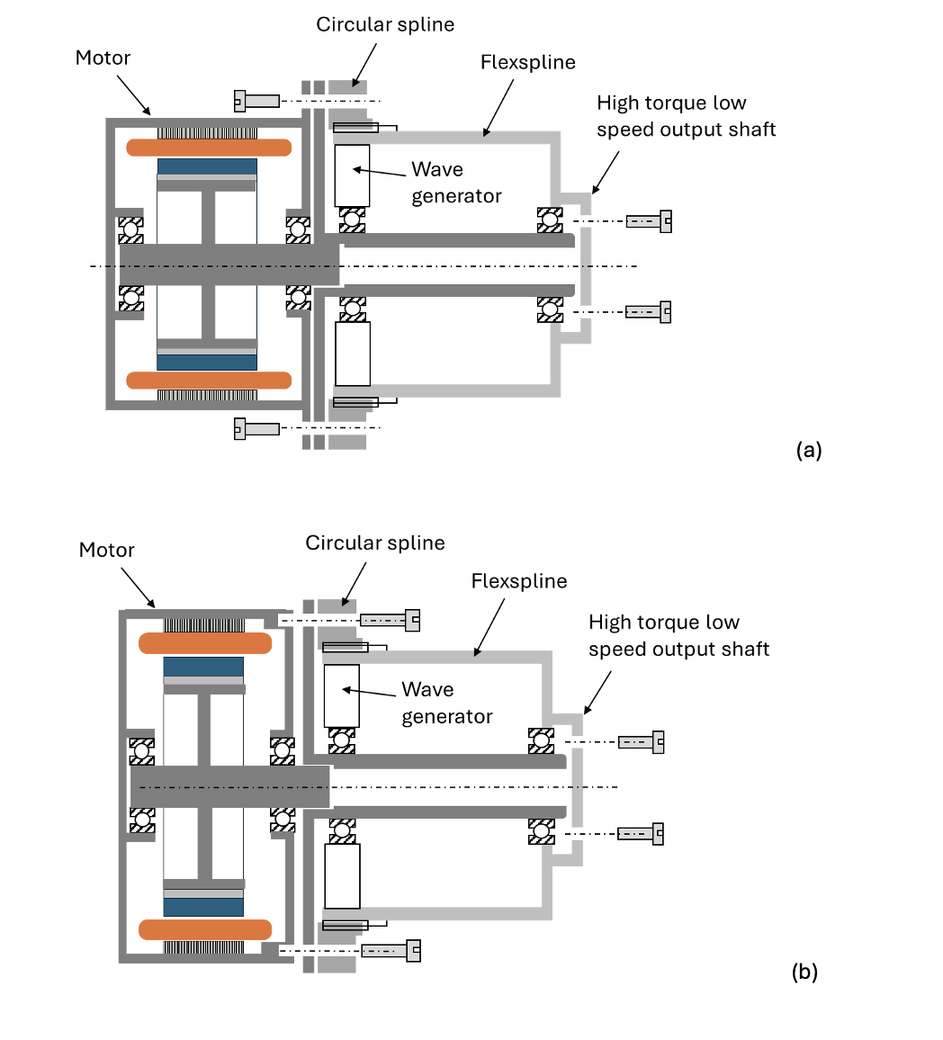
To mount a motor to a gearbox a flanged connection can be used where the parts are secured with bolts. Mounting a motor to a strain-wave gear is shown in Fig. 2. It does not represent a final design and is given here just for illustration purposes. To connect the shafts, keyways and keys can be used. Depending on the motor diameter size in relation to the gear diameter the connection can be realized in a different way: see Fig. 2, a vs Fig. 2, b.
In the same or a similar way, a motor can be integrated with any other type of gearbox.
Alva’s motors are usually more compact than conventional servo motors. The benefit is smaller mechanical footprint of the solution (Fig. 3).
%25252520and%25252520Alva%25252520solutions%25252520(b%2525252C%25252520c)..png)
Deeper integration of a motor and a gear
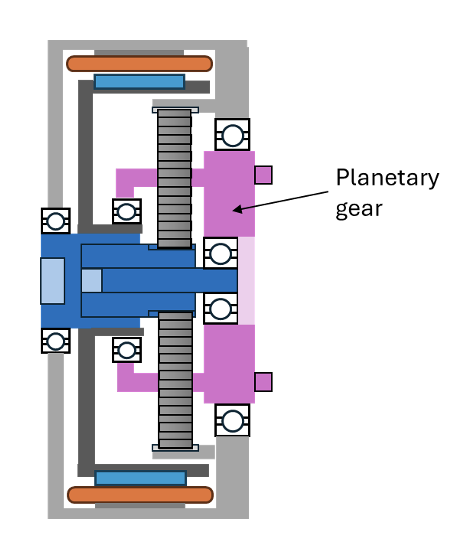
When the gearboxes’ mechanical structure can be redesigned, it opens for the solutions where the frameless motor and the gearbox elements can share parts of the joint carrying structure, such as e.g. shaft or bearings. Fig. 4 present the solutions with planetary gear integrated inside the motor.
Strain-wave gear has inner space which can be used to place a motor inside (Fig. 5). This solution requires proper thermal design to make sure adequate cooling. Realization of such exotic solutions is possible only in close cooperation between the gear and the motor manufacturers.
%2525252C%25252520out-runner%25252520motor%25252520(b)..png)

All rights reserved ©2025