Optimizing Mechatronics for Precision Metrology Applications
Understand how choosing the correct motor can improve precision and speed in metrology equipment such as coordinate measuring machines, laser trackers, and other industrial measuring applications.
January 30, 2025
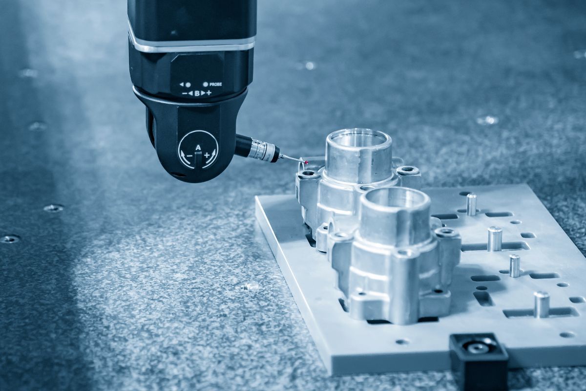
What is a Coordinate Measuring Machine (CMM) and How Do They Work?
A CMM is used to accurately measure a physical object or to create a digital copy for comparison with a virtual one. It’s typically used in the manufacturing industry to ensure products are produced with the correct quality, in engineering to reverse-engineer physical objects into digital versions, or in prototyping to streamline design and production steps.
There are many types of CMMs, but all work on the same basic principle. A sensor is moved up to or near the physical object, at which point the machine registers the global coordinates of the part along the X, Y, and Z axes. The machine’s software then builds a cloud of measuring points, which can be compared to each other, or to the digital model of the part. It is crucial that the machine knows exactly where the probe is located in space when the measuring point is recorded. This places significant importance on the quality of the incoming components and the overall design of the machine.
Not only is it important for the probe to reach the part with high precision, but it should also be flexible enough to access as many areas of a complex part as possible - and of course, it should do so quickly to save time. A typical modern CMM functions like a 5-axis CNC machine, with the standard X, Y and Z axes, as well as rotational axes A and B to tilt and twist the measuring head.
What other Metrology equipment is there?
Other types of industrial metrology equipment include rotary tables, laser scanners, radars, CT scanners, X-rays, and microscopes.
In nearly all these applications, it is necessary to rotate a probing or scanning head with high precision and repeatability. For rotary tables, one axis needs to be precisely positioned while an object is being measured. For theodolite solutions, such as laser scanners and radars, two motors control both the horizontal and vertical angles of a laser that interacts with the probing head, operated by an operator who may be over 50 meters away. If a robot arm is used to position an object or a scanning head, it adds even more joints to drive and control.
.jpeg)
Geared vs direct drive actuators: What should I choose?
To maximize the precision of these machines, it’s important to minimize the factors that can affect performance. One such factor is eliminated by using a direct drive actuator. The alternative, a geared drive, can have issues with backlash, worn gears, and vibrations. A direct drive is also lighter, requires less space, and runs more smoothly, faster, and quieter.
Cogging-torque: What is it and why does it matter?
Slotless motors are often preferred in metrology devices over slotted motors due to an important factor - cogging. Since these motors operate at low rotational speeds (or very fast) and need to position the metrology applications at various angles with high precision, even small effects like cogging can cause issues. Cogging in slotted motors is primarily caused by a variation in the magnetic attraction force between the permanent magnets and the iron core teeth of the stator as the rotor turns. This torque ripple effect causes vibrations and noise, which notably affect the measurement quality or the time required to obtain accurate results.
Since slotless motors do not face these variations in the magnetic field, cogging is virtually eliminated. Additionally, a slotless motor is smaller and lighter, which helps reduce the overall weight of the system.
Why is the motor constant important for Metrology applications?
Another factor to consider while designing the mechatronics for metrology devices is the motor constant. The higher the motor constant, the higher the efficiency of such motor, which helps limit the heat buildup in the system. Metrology machines are temperature-sensitive because heat changes the geometry of the mechanical components due to thermal expansion. If these parts assist in holding the probe, camera or laser, it will affect precision. In production environments, this also may affect how fast parts can be measured, since the motors need to cool down between scans.
Sensors and advanced software can sometimes adapt to some of these temperature changes, but a more efficient design with less temperature fluctuations is preferable. This also allows for the possibility of running angular position sequences at higher speeds, which makes the application more attractive and cost-efficient.
Should I choose a SlimTorq™ motor for a Metrology application?
Metrology applications require precise, efficient, lightweight, fast, and slim direct-drive actuators with sufficient torque. All these factors fit the profile of the Alva SlimTorq™ FiberPrinted™ slotless motors.
.png)
Additionally, lightweight components in a multi-joint system, such as a CMM, are valuable because every gram saved at the part farthest from the base reduces the need for stability in all preceding stages of the machine. This opens the possibility to either increase stability and precision, or reduce stiffness requirement, saving space, weight, and potentially reducing the cost of many components.
Contact
Nicolas Giraudo
Chief Commercial Officer
Fossegrenda 1, 7038 Trondheim, Norway
Our motors

All rights reserved ©2025